
PRODUCTS
 Mobile:+86-13615886914
Tel:+86-13615886914
QQ:2425087091
Email:liukaisheng@ifatechcn.com
Skype:sdqdlks
Add:No.798 Jinghua Road , High-tech District, Ningbo City,Zhejiang Province
Ningbo TEMAX Solutions Co., Ltd
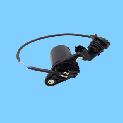
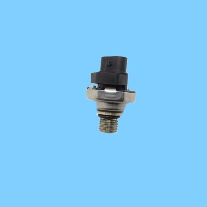
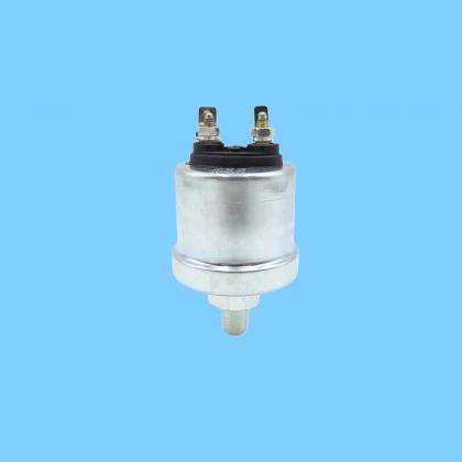
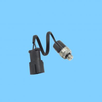
| Name: | 109-7194 Crankshaft Position / Timing / Speed Sensor |
|---|---|
Product Description
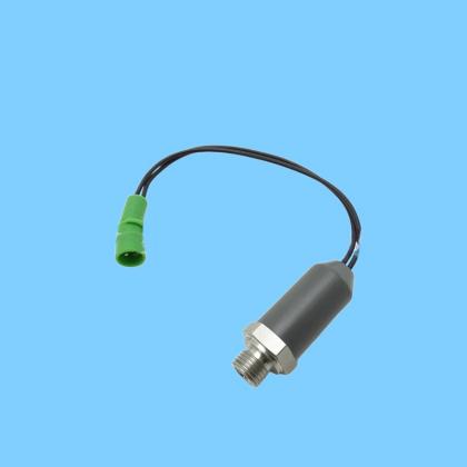
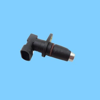
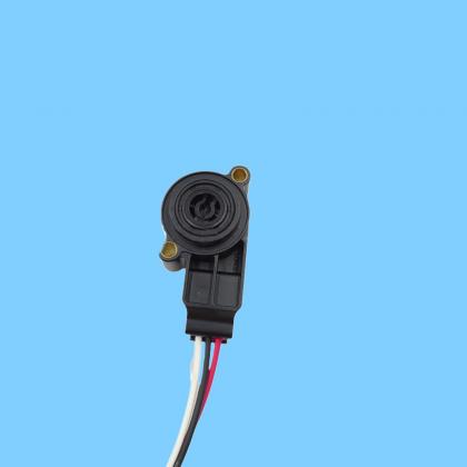
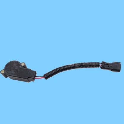
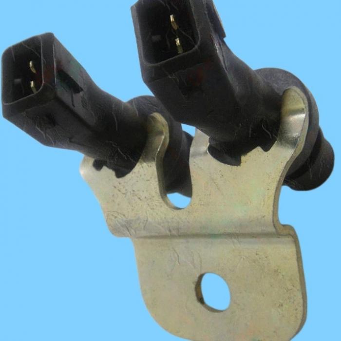
The Caterpillar 109-7194 Crankshaft Position / Timing / Speed Sensor—often referred to simply as the "Crank Position Sensor"—is designed to detect crankshaft rotational speed and position; it serves as a core component within the engine's electronic control system.
I. Key Parameters and Specifications
OEM Model: 109-7194 (Related Series: 109-7195)
Universal Replacement Models: 245-4630, 236-6221, 9047020
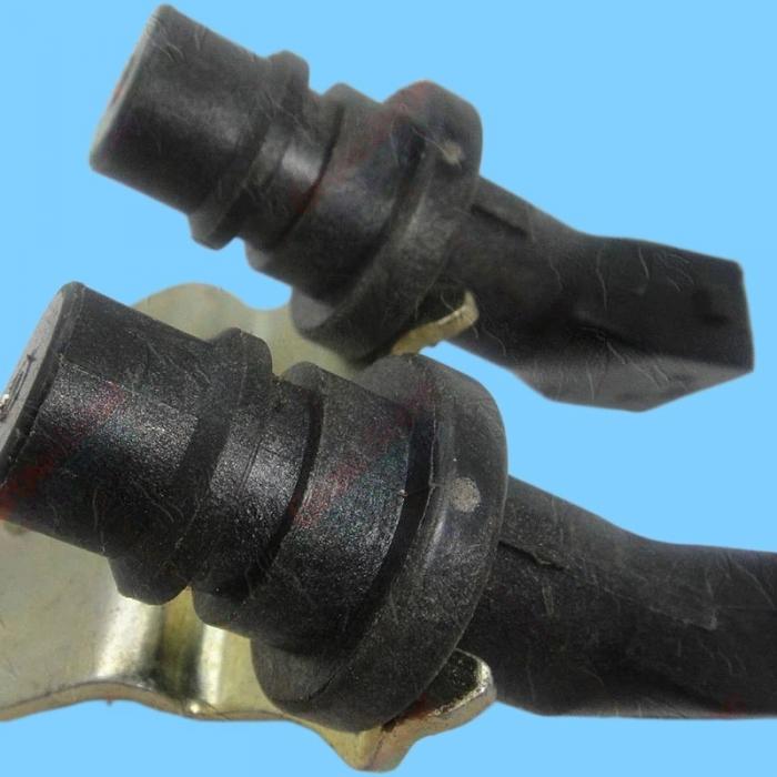
Operating Principle: Magnetic Induction (Magnetic Pulse Type); requires no external power supply
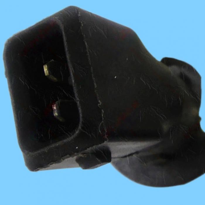
Electrical Interface: 2-Pin Connector (Signal +, Signal -)
Thread Specification: M16 × 1.5 (Common)
Internal Resistance: Approx. 700–1000Ω (at room temperature)
Output Signal: AC Pulse Voltage (Amplitude increases with engine speed)
Operating Temperature Range: -40°C to 125°C
II. Compatible Models (Caterpillar)
Primarily used in C7, C9, 3126, 3126B, 3126E, and 3116 series engines:
Excavators: 320D, 325D, 330C, 330D, 336D, E320D, E330C, E336D
Loaders / Dozers: 950H, 962H, 966H, 972H, 980H, D6N, D7R
Others: Generator Sets, Mining Equipment
III. Core Functions
Speed Measurement: Outputs a pulse frequency directly proportional to the crankshaft's rotational speed, allowing the ECM to calculate the engine's RPM.
Position Detection: Identifies the crankshaft's angular position and the piston's Top Dead Center (TDC) location to control fuel injection timing and ignition timing.
Synchronization Signal: Works in conjunction with the Camshaft Position Sensor to enable precise identification of the No. 1 cylinder's Top Dead Center. Engine Protection: In the event of signal loss, the ECM will cut off fuel injection and ignition to prevent engine damage.
IV. Common Faults and Diagnostics
Fault Symptoms:
Engine fails to start / Difficult starting
Stalling while driving, engine shaking/vibration, lack of acceleration power
Dashboard tachometer is unresponsive / displays abnormal readings
Diagnostic Trouble Codes (DTCs): P0335 (CKP Circuit Malfunction), P0336 (CKP Performance)
Basic Diagnostics:
Resistance Test: Disconnect the connector and measure the resistance between the two pins; the reading should be between 700–1000Ω. An infinite reading or 0Ω indicates a faulty sensor.
Voltage Test: Measure the AC voltage while cranking the engine; it should be **≥0.5V**. The voltage level should increase as engine speed rises.
Waveform Inspection: An oscilloscope should display a regular sine wave, free of noise or signal interruptions.
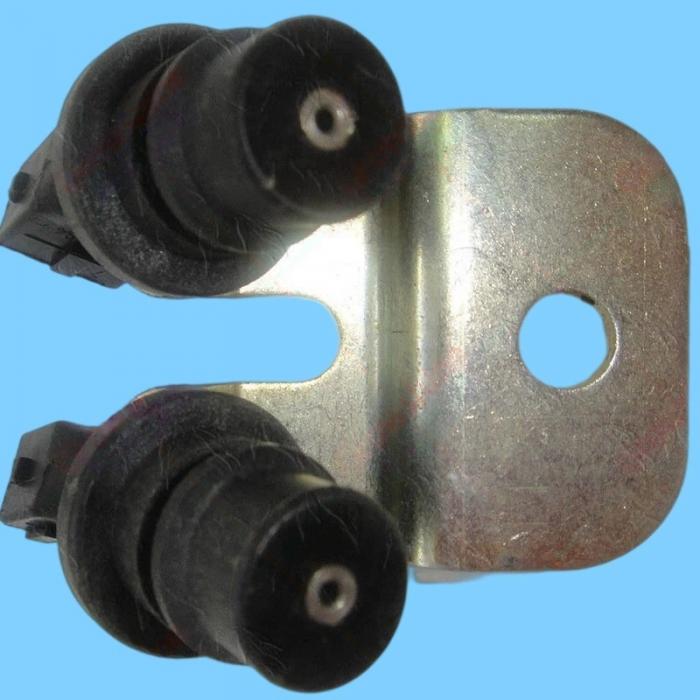
V. Installation and Replacement Guidelines
Installation Location: Typically located on the flywheel housing or the side of the crankcase, aligned with the flywheel ring gear or signal wheel.
Installation Gap: The clearance between the sensor tip and the signal gear teeth should be approximately 0.8–1.2 mm; an excessive gap will result in a weak signal.
Torque: Tighten to a torque of approximately 25–35 N·m; avoid overtightening to prevent damage to the threads.