
PRODUCTS
 Mobile:+86-13615886914
Tel:+86-13615886914
QQ:2425087091
Email:liukaisheng@ifatechcn.com
Skype:sdqdlks
Add:No.798 Jinghua Road , High-tech District, Ningbo City,Zhejiang Province
Ningbo TEMAX Solutions Co., Ltd
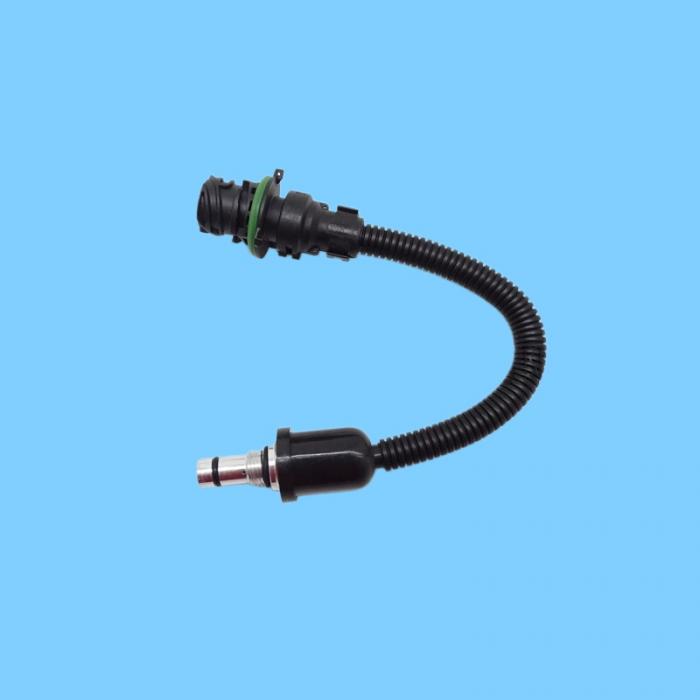
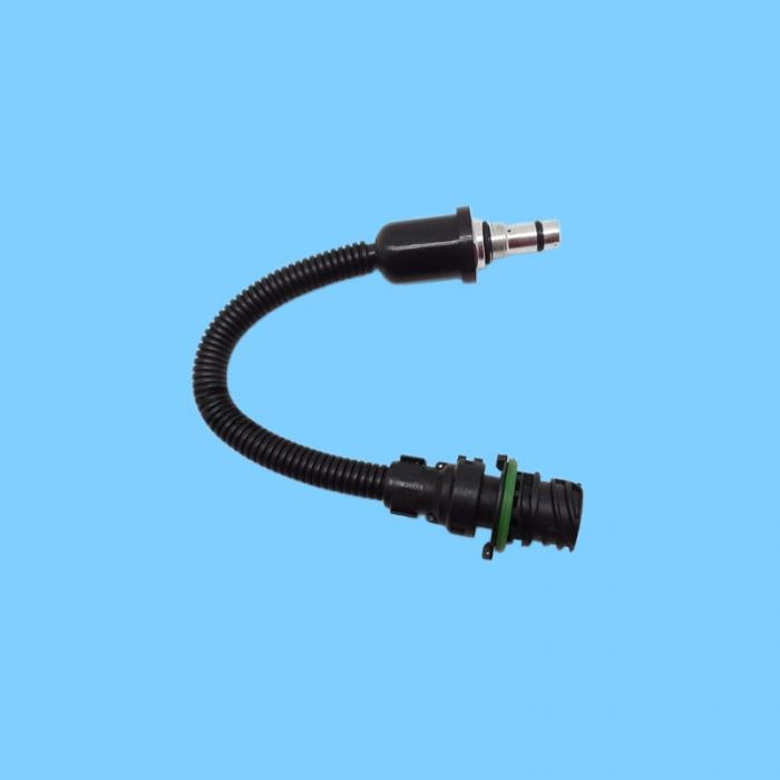
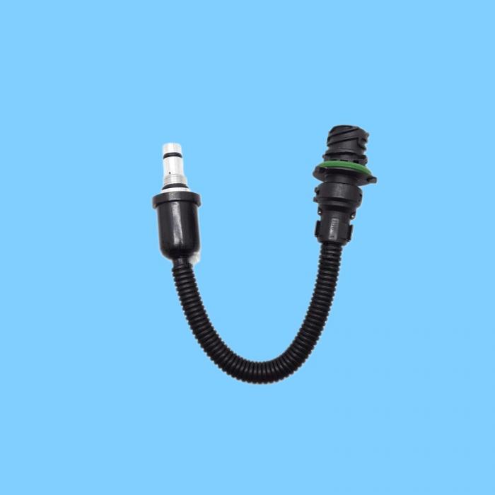
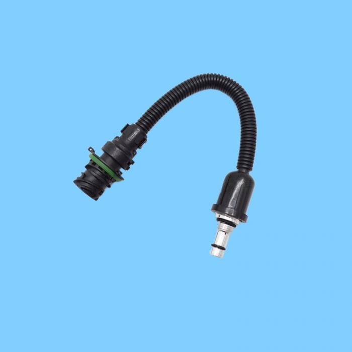
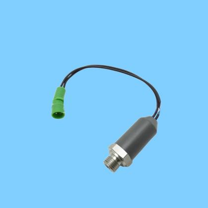
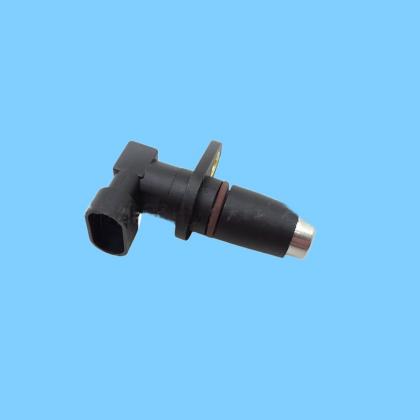
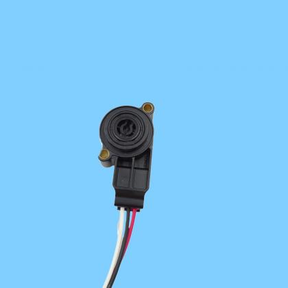
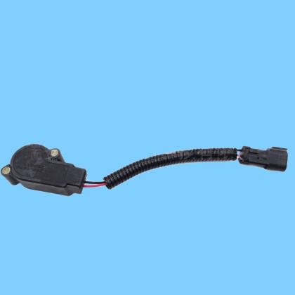
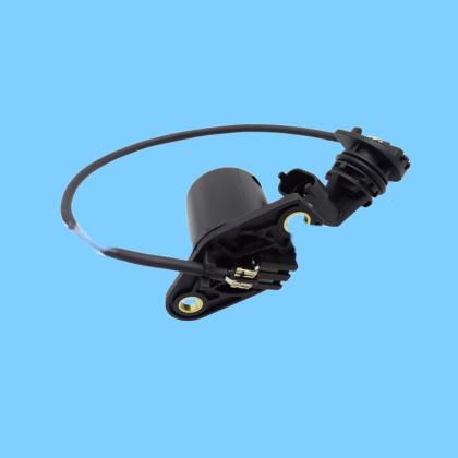
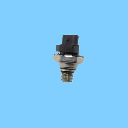
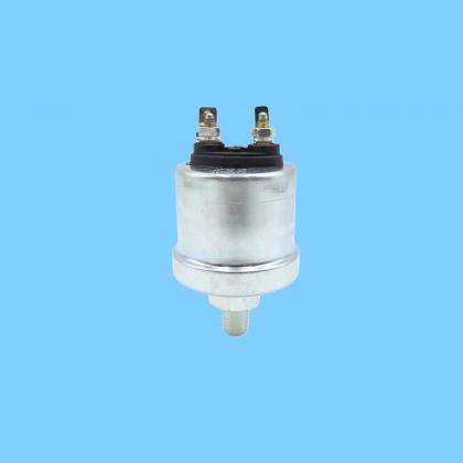
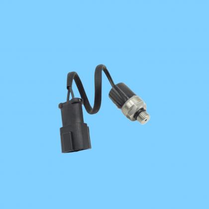
| Name: | 17286432 (VOE 17286432) — Volvo Mechanical Pressure Switch Valve |
|---|---|
Product Description
17286432 (VOE 17286432) — Volvo Mechanical Pressure Switch Valve. Primarily used in the braking, hydraulic, and air systems of articulated haulers and wheel loaders to monitor pressure and output ON/OFF signals, thereby triggering alarms or protective actions.
I. Model and Classification
OE Part Number: 17286432 / VOE 17286432 (Volvo Genuine Part)
Type: Mechanical Pressure Switch (Non-Analog Sensor)
Aliases: Pressure Switch Valve, Brake Pressure Switch, Hydraulic Pressure Switch
II. Applicable Models (Core Range)
Articulated Haulers (A-Series): A25E/F/G, A30E/F/G, A35E/F/G, A40E/F/G, A45G
Wheel Loaders (L-Series): L105, L110G/H, L120G/H, L150G/H, L180G/H, L220G/H, L250G/H, L350F/G
Others: Select Graders and Pavers
III. Key Parameters (Industry Standard)
Table
Parameter Specification
Operating Principle Diaphragm / Piston-type mechanical sensing; pressure triggers contact switching (ON/OFF)
Output Signal Discrete (Switching) Signal (NO/NC); No analog voltage output
Pressure Range Commonly 5–10 bar (for braking / hydraulic systems)
Operating Temperature -40°C to +125°C
Protection Class IP67
Electrical Interface 2-Pin Waterproof Connector
Thread Interface M12×1.5 / M14×1.5
Contact Capacity DC 24V / 5A
IV. Function and Principle
Core Function: Monitors brake air pressure and hydraulic system pressure. When the pressure falls below or rises above a preset threshold, the contact switches state, sending a signal to the ECU or instrument panel to illuminate a low-pressure warning light or to cut off power to protect the system. Principle: System pressure acts upon an internal diaphragm or piston, actuating a mechanical mechanism that causes electrical contacts to close or open, thereby achieving a conversion from "pressure" to an "electrical signal."
VI. Installation and Troubleshooting
Installation Guidelines
Install on the brake air reservoir or the main hydraulic line.
Clean the threads and sealing surfaces; replace the O-ring.
Torque: 25–35 N·m.
Distinguish between Normally Open (NO) and Normally Closed (NC) contacts to avoid reverse-logic wiring errors.
Common Faults and Symptoms
Brake warning light remains illuminated: Pressure switch failure, line leakage, or stuck contacts.
Vehicle fails to start / Speed is limited: Insufficient brake pressure causes the ECU to enter protection mode.
Contacts fail to actuate: Ruptured internal diaphragm or mechanical jamming.
Abnormal signal: Wiring harness short circuit or open circuit, or corroded connector pins.
Simple Testing
Use a multimeter (continuity mode) to test: Verify that the contacts are open or closed under normal pressure conditions, and that they switch states when pressure becomes abnormal.
No switching observed: Replace the pressure switch.
Abnormal switching behavior: Check the line pressure and verify the installation.
发送反馈