
PRODUCTS
 Mobile:+86-13615886914
Tel:+86-13615886914
QQ:2425087091
Email:liukaisheng@ifatechcn.com
Skype:sdqdlks
Add:No.798 Jinghua Road , High-tech District, Ningbo City,Zhejiang Province
Ningbo TEMAX Solutions Co., Ltd
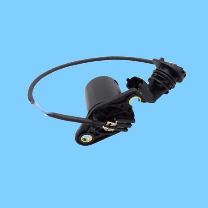
| Name: | 862289 Volvo Magnetic Speed Sensor |
|---|---|
Product Description
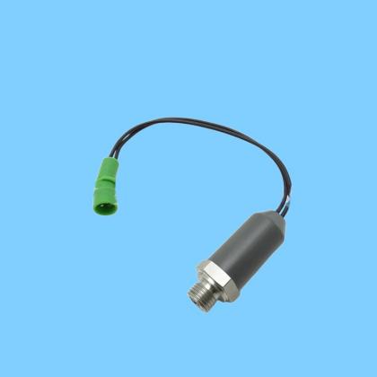
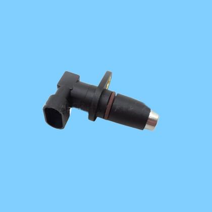
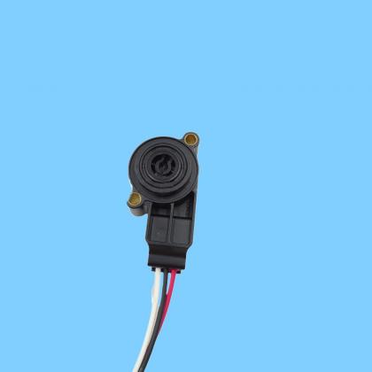
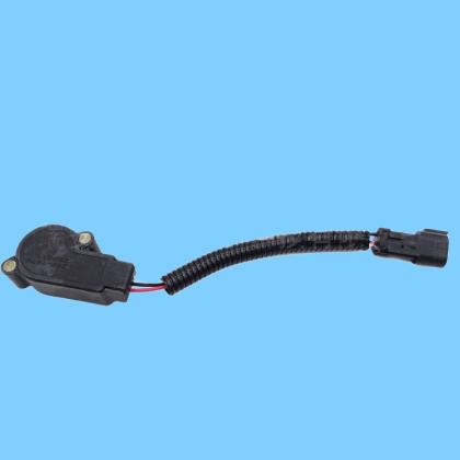
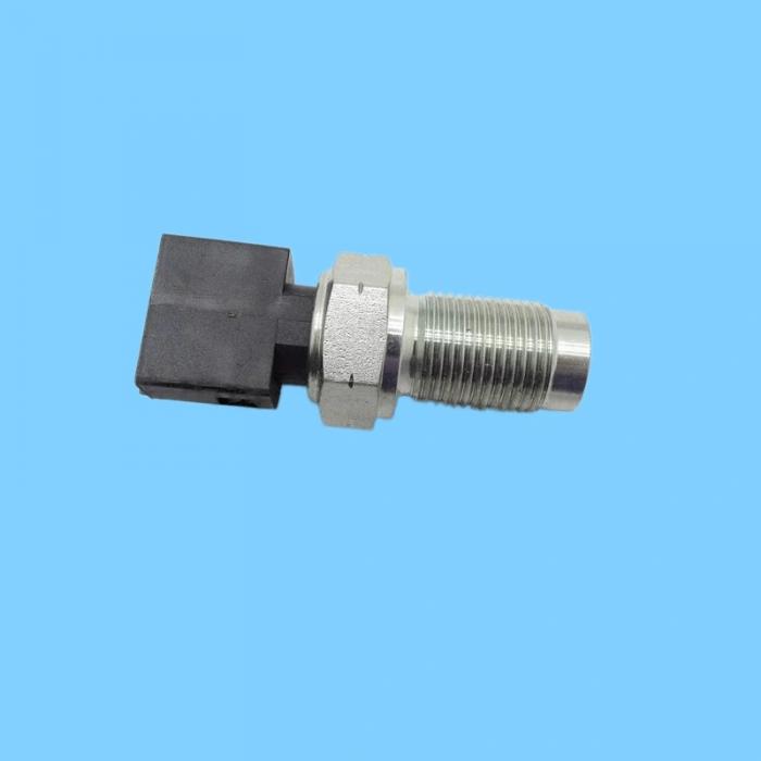
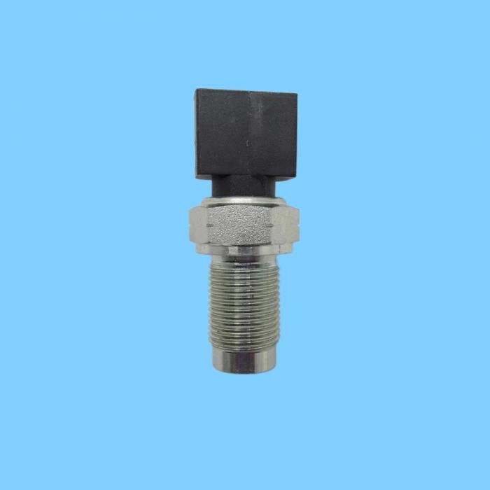
862289 Volvo Magnetic Speed Sensor (Crankshaft/Flywheel Speed Sensor)—specifically designed for engines and construction machinery—monitors engine speed and crankshaft position, providing ignition and fuel injection timing signals to the ECU. I. Core Positioning and Model Information
Model: 862289 (Volvo Genuine OE Part Number)
Type: Magnetic-Electric (Passive) Speed / Position Sensor (Non-Hall Effect; requires no external power supply)
Aliases: Tachometer Sensor, Crankshaft Position Sensor, Flywheel Sensor
II. Applicable Models (Core Applications)
Engines: Volvo TAD1232GE, TAD1642GE, TAD734GE, TAD941GE, and other series of diesel engines
Host Equipment:
Volvo Excavators (EC Series) and Wheel Loaders (L Series)
Generator Sets, Pavers, Road Rollers, and other construction/industrial machinery
III. Key Parameters (Industry Standard)
Table
Parameter Specification
Working Principle Magnetic-Electric Induction (Generates an AC signal by cutting through magnetic flux lines)
Power Supply Passive (Requires no external power source)
Output Signal Sine wave / AC pulses; amplitude increases as rotational speed rises
Installation Gap 0.8–1.5 mm (Gap between the sensor and the flywheel ring gear; critical for signal integrity)
Operating Temperature -40°C to +125°C
Protection Rating IP67 (Dustproof and waterproof; suitable for construction site environments)
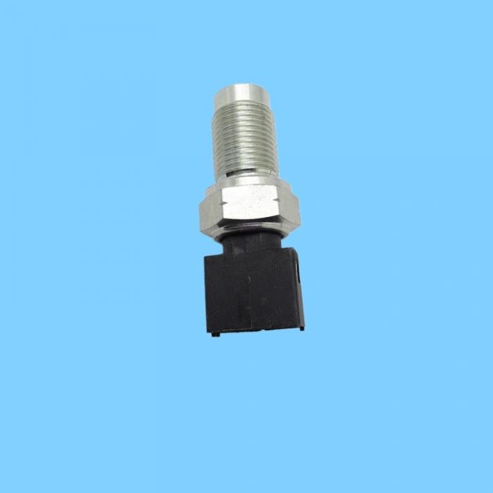
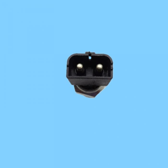
Electrical Interface 2-pin / 3-pin waterproof connector (Standard for construction machinery)
Threaded Interface Commonly M16×1.5 or M18×1.5
IV. Function and Working Principle
Core Functions: Monitors flywheel/crankshaft rotational speed; provides crankshaft position signals; facilitates control of fuel injection timing, ignition timing, idle speed stabilization, and fault diagnostics
Working Principle: The sensor contains a built-in permanent magnet and coil. As the flywheel ring gear rotates and cuts through the magnetic flux lines, the coil generates an induced alternating voltage signal, which the ECU then uses to calculate rotational speed and position.
VI. Installation and Troubleshooting
Installation Essentials
Strictly maintain the installation gap between 0.8–1.5 mm; an excessive gap results in a weak signal, while an insufficient gap risks wearing down the ring gear teeth.
Clean the mounting hole and the sensor's sensing face to ensure they are free of metal shavings, oil, and grease. Tighten to the standard torque (approx. 25–35 N·m); avoid overtightening to prevent thread damage.
Inspect the wiring harness and connector plug to ensure there is no damage, corrosion, or looseness.
Common Faults and Symptoms
Hard starting / Failure to start: The ECU receives no RPM signal, preventing it from controlling fuel injection or ignition.
Unstable idle, vibration, stalling: Abnormal signals disrupt fuel injection timing.
Poor acceleration, high fuel consumption: Loss of RPM signal results in restricted power output.
Diagnostic Trouble Codes (DTCs): P0335 (Crankshaft Position Sensor Circuit Malfunction), P0336 (Signal Range / Performance Malfunction).
Simple Testing
Use a multimeter set to the AC voltage range to measure the output terminal; while rotating the flywheel, a signal of 0.5–5V AC should be observed (voltage increases with RPM).
No signal: The sensor's internal coil is open-circuited or short-circuited, or the installation air gap is abnormal.
Weak signal: The air gap is excessive, ferrous debris has adhered to the sensor's magnetic tip, or there is poor contact within the wiring harness.
发送反馈