
PRODUCTS
 Mobile:+86-13615886914
Tel:+86-13615886914
QQ:2425087091
Email:liukaisheng@ifatechcn.com
Skype:sdqdlks
Add:No.798 Jinghua Road , High-tech District, Ningbo City,Zhejiang Province
Ningbo TEMAX Solutions Co., Ltd
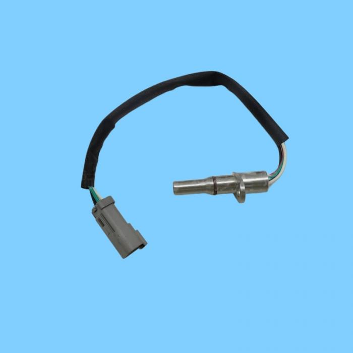
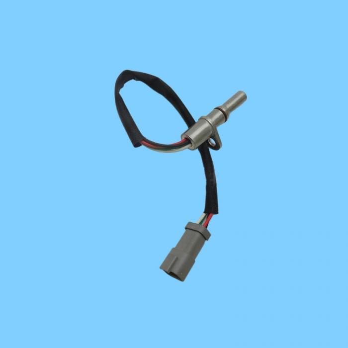
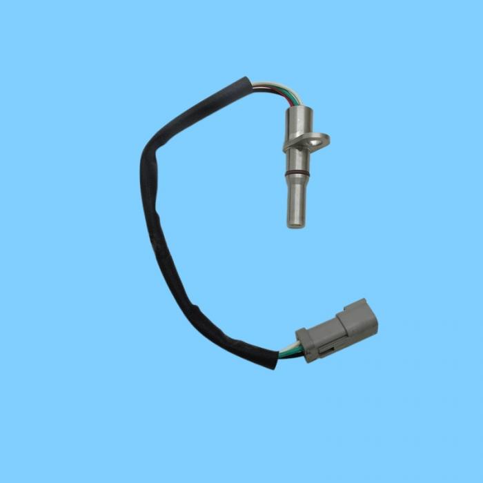
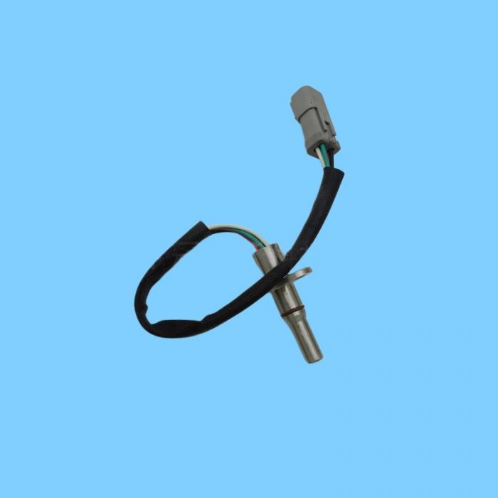
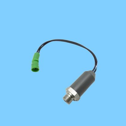
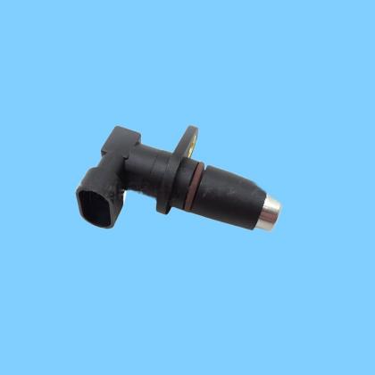
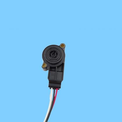
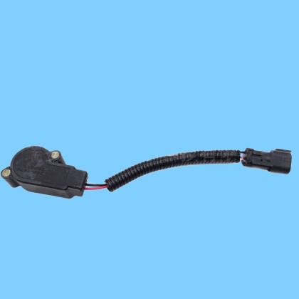
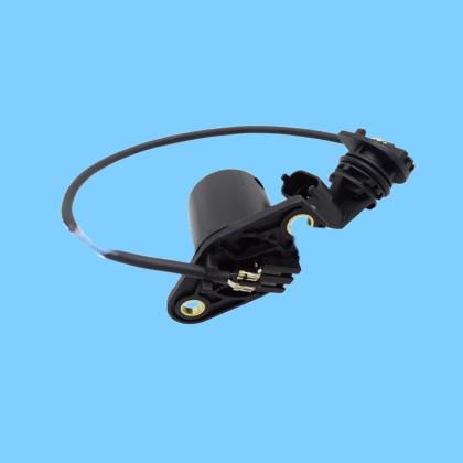
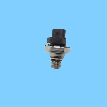
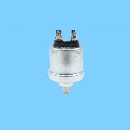
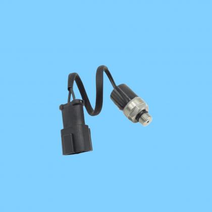
| Name: | 262-3764 (2623764)Speed & Direction Sensor |
|---|---|
Product Description
I. Core Parameters and Specifications
OEM Part Number: 262-3764 (2623764, CA2623764)
Official Name: Dual Hall Effect Speed & Direction Sensor
Type: Active Dual Hall (incorporates 2 internal Hall elements)
Core Functions:
Monitors engine / hydraulic motor speed
Detects rotational direction (A/B signal phase difference of 90°)
Electrical: 4-wire system (Power +, Power -, Signal A, Signal B); Supply Voltage: 8–32V; Square wave pulse output
Mechanical: Fixed nose length design; Threaded mount; IP67 Protection Rating; Operating Temperature: -40°C to 125°C
Compatible Gear Profiles: Compatible with standard Cat speed-sensing gears (gear pitch matches the spacing of the dual Hall elements)
II. Compatible Engines and Equipment (Mainstream Models)
Engines (Speed + Direction Monitoring)
C2.2, C3.3, C3.3B, C3.4, C3.4B, C3.8, C4.4, C7.1, 3044C
Equipment (Loaders / Compactors / Motor Graders)
Skid Steer Loaders: 226D, 232D, 236D, 242D, 246C, 246D, 256C, 262C, 262D, 272C, 272D
Multi-Terrain Loaders: 257D, 259D, 277C, 287C, 297C
Vibratory Compactors: CB-44B, CB46B, CB54B, CB7, CB8, CD-44B, CD8
Motor Graders: 120 Series
IV. Failure Symptoms and Diagnostics
Typical Symptoms
Engine tachometer displays no reading / erratic readings
Difficulty starting, unstable idle, abnormal power output
Abnormal hydraulic system operation (loss of direction / speed control)
ECM-related faults Speed Sensor Circuit / Signal Anomaly, Direction Detection Fault Code
Quick Check
Measure supply voltage (8–32V) and ground connection to verify they are normal.
Crank the engine/motor, and use an oscilloscope to measure the A/B signals (square waves with a 90° phase shift should be observed).
Check for loose connectors, corrosion, or water intrusion; also verify the gap between the sensor and the gear (0.5–1.5 mm).