
PRODUCTS
 Mobile:+86-13615886914
Tel:+86-13615886914
QQ:2425087091
Email:liukaisheng@ifatechcn.com
Skype:sdqdlks
Add:No.798 Jinghua Road , High-tech District, Ningbo City,Zhejiang Province
Ningbo TEMAX Solutions Co., Ltd
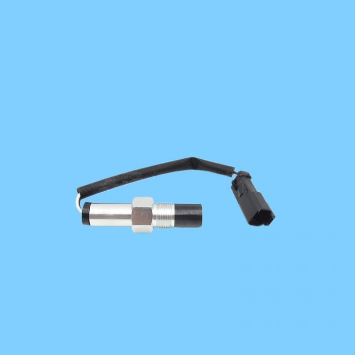
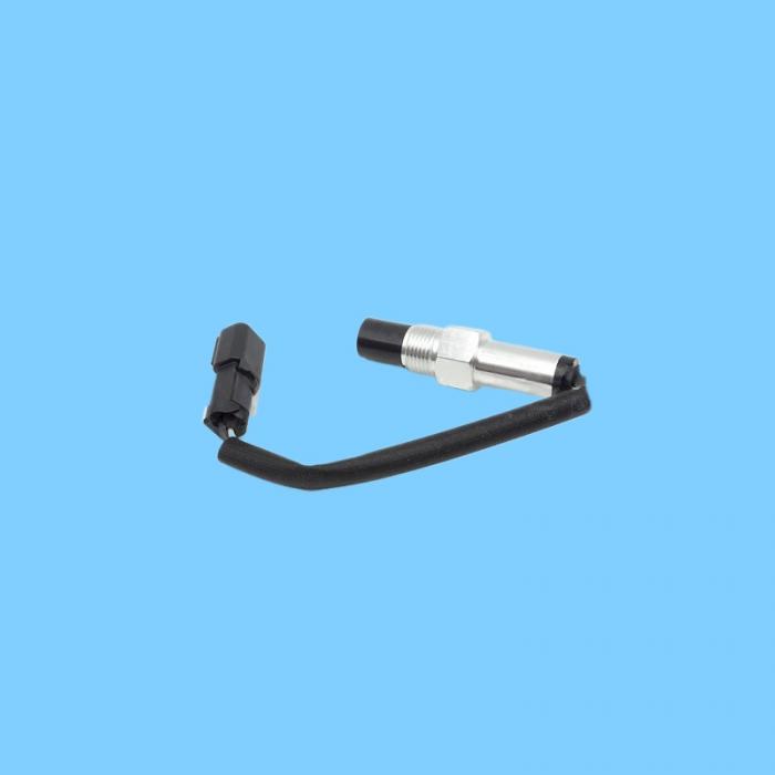
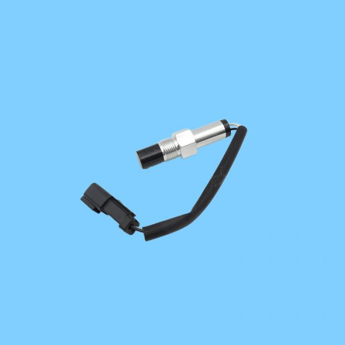
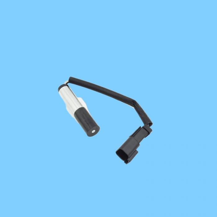
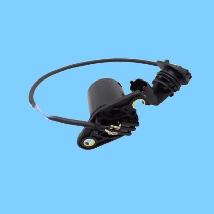
| Name: | 122-8863 (1228863) Low-Output Magnetic Speed Sensor |
|---|---|
Product Description
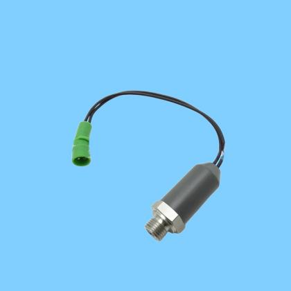
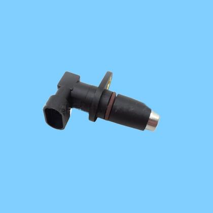
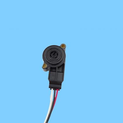
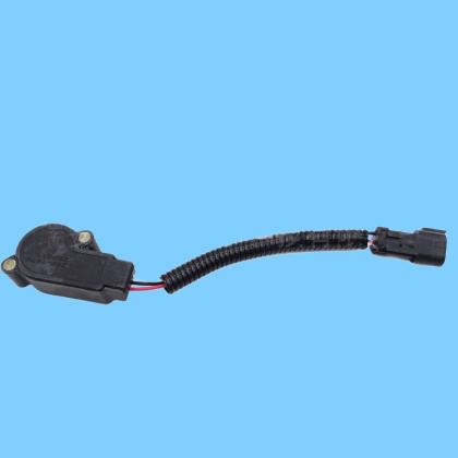
122-8863 (1228863) Caterpillar Low-Output Magnetic Speed Sensor—primarily used to monitor the rotational speed of the engine crankshaft, flywheel, or transmission, and to provide speed signals to the ECU. I. Core Basic Information
Part Number: 122-8863 (1228863)
Type: Magnetic Pickup Speed Sensor (Passive / Low Output)
Brand: Caterpillar
Function: Detects the rotational speed of moving components and outputs a pulse signal to the ECU; used for engine timing, idle speed control, transmission shifting, and overspeed protection.
II. Key Technical Specifications
Electrical: 2-Pin Connector (CAT Standard); Passive Magnetic Induction (requires no external power supply)
Thread Specification: 3/4"-16 UNF (External Thread)
Thread Length: 1.35 inches (approx. 34.3 mm)
Operating Temperature: -40°C to +125°C
Material: Metal housing, sealed probe; resistant to vibration and oil/contaminants
System Compatibility: Universal for 12V/24V Electronic Control Systems
III. Primary Compatible Engines
3126, 3176C, 3406, 3412E
C7, C9, C27, C32, and other large electronically controlled engines
IV. Primary Compatible Equipment
Excavators
312B, 320B, 330B, 345B
Loaders / Wheel Dozers
938G, 950G, 962G, 990K, 992K, 993K, 844K, 854K
Dozers
D6R, D6T, D7R, D10R
Motor Graders
12H, 120H, 140H, 143H, 163H, 24H
Articulated / Off-Highway Trucks
725, 730, 735, 772G, 773E/F/G, 775E/F/G, 777E/F/G
V. Alternative Models 122-8864 (Same series; high-output version)
189-5769, 245-4630, 318-8856 (Common OEM replacement part numbers)
VII. Common Faults and Replacement Guidelines
Fault Symptoms
Engine fails to start or is difficult to start
Tachometer displays no reading or fluctuates erratically; ECU reports a speed sensor fault (e.g., P0335, P0336)
Unstable idle speed, insufficient power, or abnormal transmission shifting
Replacement Guidelines
Install onto the flywheel housing or transmission housing, ensuring proper alignment with the signal gear ring
Clean the mounting bore to ensure the clearance between the sensor probe and the gear ring is within the normal range (0.8–1.5 mm)
Tighten to the specified torque (approximately 40–50 N·m)
Perform a test run after installation to verify the tachometer display and engine operating status